The meaning of 'maximum frequency' is not well defined as the source time functions fall of smoothly towards high frequencies and the maxium frequency then corresponds to a chosen amplitude ratio. For the seismology community, this lead to the rule of thumb that one element per wavelength at the maximum frequency is sufficient for many applications. This is because the seismograms contain very little energy at this frequency.
Dispersion Error
The numerical dispersion error has two main contributions, one from the spatial and one from the temporal discretization. The temporal dispersion error can be controlled by the chosen time step (up to the stability limit often dictated by geometrical constraints) and time integration scheme. On the other hand, the spatial error of the spectral element scheme can be controlled by element size and polynomial order.
h- vs p-Refinement
In finite-element slang, usually refers to the grid spacing or size of the elements - even if the element sizes may vary within the domain. In contrast, refers to the polynomial degree of the finite-element test functions.
Consequently, -refinement means to decrease the element size, i.e., use more elements to cover the same domain, and, respectively, -refinement means to increase the polynomial degree within the elements.
While the total number of elements remains the same in the latter case, both strategies increase the total number of degrees of freedom (dofs).
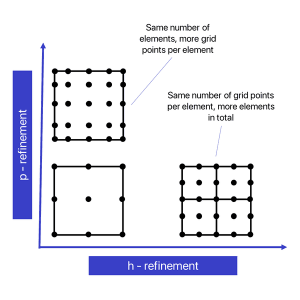
On the first glance, it may look as if both strategies give a very similar result. However, the differences are important.
One key motivation behind the spectral-element method is that a higher polynomial degree quickly reduces the approximation error. Hence, for larger values of fewer grid points per wavelength are typically sufficient to obtain the same accuracy.
So why should we not always do -refinement and choose as high as possible?
There are two main limiting factors. The algorithmic intensity increases with higher as more dofs contribute to the computation of the test functions or their gradients within the elements.
Furthermore, the model parameters are smooth within the elements by construction, and discontinuities in the medium properties can only occur across element boundaries. Thus, in media with sharp interfaces the size of the layers may limit the maximum element size.
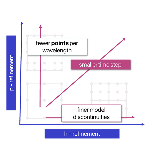
Therefore, one needs to find a good balance between element size and polynomial degree. In practice, is the most widely used choice for .
Finally, as both methods increase the number of dofs, the spacing between grid points decreases, which in turn necessitates a smaller time step due to the CFL condition. Note that even if the total number of dofs is the same for both cases in the example above, the location of the grid points is slightly different, which might have an effect on the stability limit of the time step.
How to determine the element size
The total spatial dispersion error increases linearly with the propagation distance from the source to the receiver, when the distance is expressed in number of wavelengths. It is thus useful to consider the error that is accumulated for each cycle that the waves go through and this can be derived approximately as a function of the number wavelengths per element and polynomial order :
In practice, the following figure showing this relation can be used to determine , which is needed to compute the local minimum element size from the maximum frequency and the velocity model and a mandatory input to all automatized meshing routines in salvus.
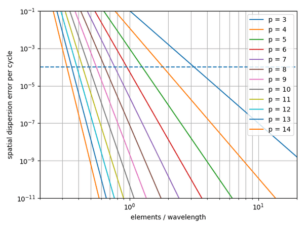
For example, if we consider an error of 1% on the seismogram acceptable and want to propagate waves for 100 wavelength in distance, the dispersion error per cycle should be , indicated by the blue dashed line. Using a 4th order scheme then suggests to use about 2 elements per wavelength in the mesh.
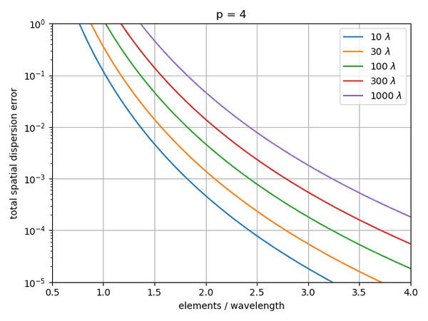
To be more explicit for the most popular order , the following figure shows the total dispersion error for various propagation distances in terms of wavelengths :
How to determine the time step
The choice for the time step has two main critieria: firstly, explicit time stepping schemes as typically used in the spectral element method are conditionally stable. This means that there exists a maximum time step at which the simulation becomes unstable and this limit is provided by the CFL (Courant–Friedrichs–Lewy) condition:
Here is the Courant number that is specific to the time scheme, is the dimension of the problem, is the spectral radius that depends on the spatial discritization scheme, is the element size and is the velocity. The minimum of this expression on the whole domain is a necessary condition for stability and is used by default if the user does not provide a time step. However, this may not be a sufficient criterion for the required accuracy.
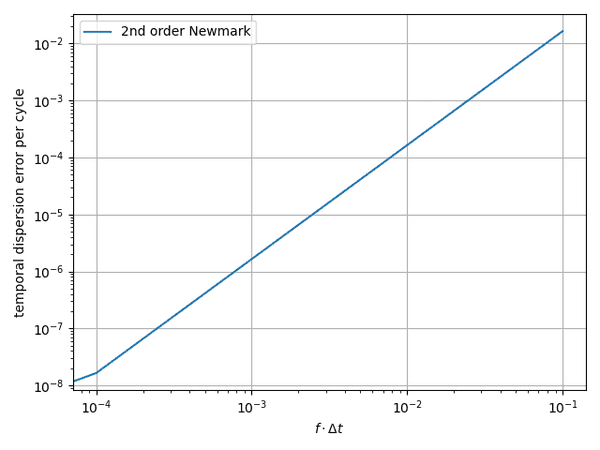
As a second criterion the temporal dispersion error needs to be limited similar to the spatial error discribed above. The temporal dispersion error can be expressed as
For the 2nd order Newmark scheme that Salvus uses the constants take the values and . The following figure shows dispersion error per cycle as a function of the time step times the frequency :
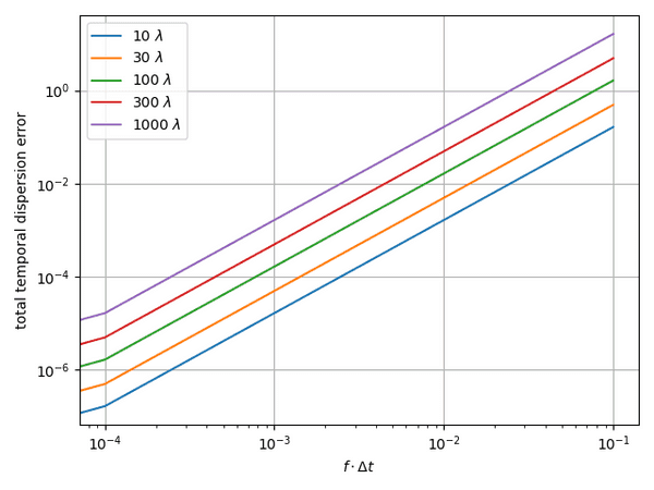
To be more explicit, we again show the total dispersion error for several propagation distances:
 Mondaic